CELLS, OHM'S LAW AND RESISTORS
INTRODUCTION
Electric current I (SI unit Amperes, A) is defined as the number of electrons Q (SI units, Coulombs, C) passing a particular point in unit time t (SI units, seconds, s) that is;

The flow of electric current constitutes what is referred to as electricity. Current flows between two points if there exists a potential difference between them. Potential difference occurs when one point is more positive (considered as positive terminal) compared to the other (considered as negative terminal).
There are various sources of electricity among them;
- Chemical Reaction (cells and batteries)
- Electromagnetic induction (changing magnetic field)
CELLS
A cell is a single source of electricity that employs chemical reaction to produce current. It converts chemical energy into electrical energy. A cell comprises two electrodes (terminals) and an electrolyte. Electrodes are conductors through which current flows while the electrolyte is a substance with free ions. Cells can either be un-chargeable or rechargeable (accumulators).
Broadly, cells are classified into two:
- Wet cells
- Dry cells.
Like the names suggest, wet cells contain a liquid electrolyte while dry cells contain a moist solid electrolyte. Example of a wet cells are the simple cell and the lead-acid cell where the electrolyte is a mixture of sulphuric acid and water. Examples of dry cells are zinc-carbon cell (also known as lechlanche cell) and alkaline-cell. The zinc-carbon/lechlanche cells produce electricity from the electrochemical reaction between zinc and manganese four oxide (MnO2) in the presence of an electrolyte which is either ammonium chloride or zinc chloride dissolved in water. Zinc acts as the anode and the manganese four oxide the cathode, although carbon is added to the cathode to increase conductivity and retain moisture.
Wet cells
(1) Simple cell
A simple cell can be made by dipping two different metal electrodes of different reactivities in an electrolyte such as an alkaline or a dilute acid solution, or even a fruit such as an orange or a lemon. An example of a metal-pair commonly used as electrodes is zinc and copper since zinc is more reactive than copper. The greater the difference in reactivity the higher the voltage. The two electrodes are connected together by a conducting wire to complete the circuit. Common electrolytes used include dilute NaCl and H2SO4. The compounds are diluted with water so as to break them into ion-pairs. Example;

When zinc and copper plates are dipped in the dilute sulphuric acid, the zinc plate starts dissolving into the electrolyte as Zn2+ ions (cations), with each zinc ion leaving two electrons behind, a process called oxidation. The zinc plate becomes the negative electrode (anode) and acts as a source of the electrons that flow through the connecting wire to the copper plate. The zinc ions Zn2+ react with the SO42- in the electrolyte to form zinc sulphate.
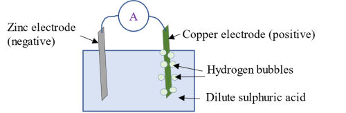
As soon as the zinc ions enter the electrolyte, an equivalent number of hydrogen ions H+ leave the solution for the copper plate, where they receive electrons e- (anions) from the copper thereby becoming neutral hydrogen gas. The copper plate on losing electrons (a process called reduction) becomes the positive electrode (cathode) which enables it to attract the electrons from the zinc electrode. This movement of electrons constitute an electric current (hence an ammeter in the circuit is deflected). When current flows through a load in an external circuit, the cell discharges. (NOTE: The products of oxidation reaction at the anode (zinc plate) are positive ions or cations while the products of reduction reaction at the cathode (copper) are electrons or anions). The hydrogen gas formed collect as hydrogen bubbles on the surface of the copper plate, a process referred to as polarization. Some hydrogen bubbles escape into the air while some remain on the surface of the copper plate. As the bubbles pile up, they create a barrier between the copper plate and the electrolyte thereby reducing the rate of chemical reaction. The output current therefore decreases.
(2) Lead-acid accumulator
A lead-acid accumulator is a wet but rechargeable cell. Rechargeable cells are also referred to as secondary cells or accumulators. Lead-acid accumulators are constructed with ebonite, glass or hard rubber placed on the top to eliminate any kind of electrolyte discharge. It uses sponge lead (Pb) as the negative electrode and lead peroxide (PbO2) as the positive electrode, with dilute sulphuric acid as the electrolyte where;

During the discharging process (cell is connected to an external circuit), oxidation reaction takes place at the lead electrode. The lead electrode reacts with, and loses positive charges to, SO42- ions, forming lead sulphate and leaving the electrode with a net negative charge. The lead electrode therefore acts as a source of electrons. Lead sulphate formed during the oxidation action collects as a white coating around the lead electrode.
As soon as SO42- ions move to the sponge lead electrode, an equivalent number of H+ ions leave for the PbO2 (lead peroxide) electrode where they receive electrons leading to the production of lead sulphate. On losing the electrons, the lead peroxide electrode becomes positively charged, with the lead sulphate formed during the reduction action being deposited on the electrode as a thin white layer. The positive electrode attracts electrons from the negative electrode through the external circuit. This flow of electrons constitutes an electric current. The potential difference between the two electrodes reduces with time as current flows through the external circuit (discharges). NOTE: Both the anode and the cathode are covered by a white layer of lead sulphate during discharge. The coating is responsible for the voltage drop during usage of the cell as it increases the resistance of the electrodes.
To charge a lead-acid accumulator, an external DC source is applied to the accumulator. The negative terminal of the DC source is connected to the negative terminal (Pb) and the positive terminal of the DC source connected to the positive terminal (PbO2). At the negative terminal (anode), the electrons injected by the negative terminal of the DC source repel the sulphate ions SO42 back into the electrolyte. Reduction action therefore occurs as opposed to oxidation action that occurred when the cell was discharging. The reduction action converts the negative electrode into pure lead, returning it to the state it was before the cell was discharged. At the positive electrode (cathode), the applied positive potential attracts electrons from the electrolyte back to the electrode (oxidation occurs as opposed to reduction) turning it back to the state it was before the cell discharged.
NOTE 1: There are three ways of determining when an accumulator is fully charged:
- the final current level
- the peak charging voltage while this current flows
- the colour on the positive plate. It is dark brown when the accumulator is fully charged (only visible if the cell has transparent cover).
NOTE 2: The caps of the cell are usually left open when charging a lead acid accumulator to allow for the escape of hydrogen and oxygen gases formed during the charging process.
NOTE 3: The ratio of density of a liquid to that of water at the same temperature is called relative density. The relative density of a fully charged accumulator is 1.26. When a lead-acid accumulator is discharging, the relative density of the electrolyte reduces as the sulphur (in sulphuric acid) move to the plates. The accumulator is usually topped up with distilled water to maintain the relative density of the electrolyte. Relative density is measured using a hydrometer.
Dry cells
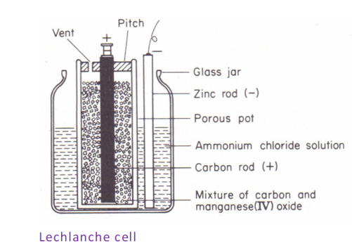
(1) Zinc-carbon/lechlanche
The zinc-carbon/lechlanche cells produce electricity from the electrochemical reaction between zinc and manganese four oxide (MnO2) in the presence of an electrolyte which is either ammonium chloride or zinc chloride dissolved in water. Zinc acts as the anode and the manganese four oxide the cathode, although carbon is added to the cathode to increase conductivity and retain moisture.
(2) Zinc-Alkaline cells
Zinc-Alkaline cells operate in a similar way as the lechlanche cell. However, they utilize manganese dioxide as the positive electrode as opposed to carbon though they have zinc as the negative electrodes. Also, zinc alkaline cells use potassium hydroxide as the electrolyte solution as opposed to ammonium chloride solution.
ELECTRICAL CIRCUIT AND OHM'S LAW
An electrical circuit is a continuous connection between points through which an electric current flows. It is made up of three main component:
- Source of electric power for example a cell
- Conductive path for example a wire through which the current flows
- A load that needs power for example a lamp
The voltage across a cell when it is not connected to an external circuit is called electromotive force (EMF) while the voltage across the same cell when connected to an external circuit is the potential difference (p.d). EMF is usually greater than the pd. This is because when the cell is in operation, some of the EMF is used to overcome internal resistance of the cell. Resistance limits the flow of an electric current. This means that current flowing through an external circuit can also be controlled through the use a resistive material , for example a resistance wire or a resistor. A resistor is a component of a circuit specially designed to control the amount of current in a circuit.
The relationship between potential difference, V, current I and resistance R is summarised in Ohm's law . According to the law, the voltage V in a circuit is directly proportional to the current I flowing through the circuit, other factors constant. That is;


Where R is a constant of proportionality called resistance. The SI unit for resistance is Ohm (Ω). The higher the resistance, the lower the current in the circuit and vice versa. For a resistance wire, the resistance R increases with length l and cross-sectional area A. Resistance also depends on the type of material used. Some materials such copper offer low resistance to the flow of current. it is for this reason that they are used as connecting wires in circuits.
Ohmic and non-Ohmic conductors
Materials that conduct current are referred to as conductors (have low resistance to the flow of current) while those that do not conduct current are called non-conductors or insulators (exhibit high resistance to the flow of current). Conductors have free electrons. The movement of the electrons when a potential difference is applied across a conductor constitutes an electric current. The electrons in insulators on the other hand are tightly bound to the atom hence are not free to move even if a potential difference is applied (unless it is excessively large that it rips the electrons off the atoms). Materials whose conductivity lies between that of a good conductor and a good insulator are called semiconductors. Current flow in semiconductors is due to charge carriers, electrons and holes.
It is important to note that in conductors, resistance increases with temperature while in semiconductors, the resistance decreases with temperature. Additionally, materials that obey Ohm’s law are referred to as Ohmic conductors (for example most wires) while those that do not are called non-ohmic conductors (for example semiconductors). Ohmic conductors have a linear relationship between current and voltage while non-Ohmic conductors have a non-linear relationship between current and voltage. Ohmic conductors become non-ohmic when current per cross-sectional area exceeds some threshold value.
Resistors
A resistor is an electrical component that limits or regulates the flow of current in a circuit and also to provide a specific voltage for an active device such as a transistor. There are different types of resistors among them;
(i) Thermistors:
These are resistors for which the resistance changes as temperature thermistors are often used as temperature sensors or heat protection devices.
(ii) Variable resistors:
The resistance is adjustable. The resistors are used as potential dividers (potentiometers) or to control the amount of current in a circuit (rheostat).
(iii) Fixed resistor:
These are the most common resistors. Fixed resistors are constructed with a constant resistance value which is not influenced by environmental factors such as temperature. Most fixed resistors have a pattern of coloured bands (colour code) that indicates the resistance value as well as tolerance (percentage error of the resistor). The number of bands ranges from three to six although four-band resistors are the most common. The bands are read from left to right with silver of gold often coming last. For a 4-band resistor, the first band colour represents the first digit of the resistance value, the second band colour the second digit, the third band colour the multiplier and the last band colour the tolerance. The colours are matched to a colour code chart and the resistance evaluated.
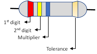
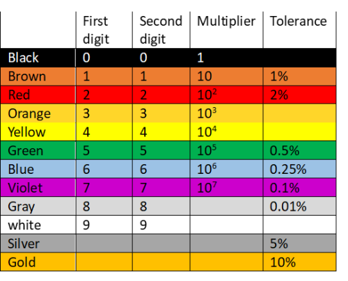
For the resistor above, the resistance is equal to:


Resistor arrangement
Resistance is associated with a voltage drop. For example, say current I flows through a resistor of resistance R.
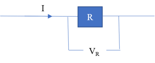
The voltage drop VR is given by;
 (i)
(i)
Suppose that the current is supplied by a source of potential difference V.
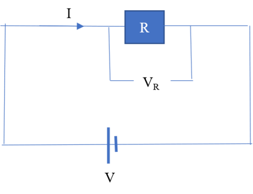
It follows that the supply voltage is equal to the voltage drop across the resistor, that is:
 (ii)
(ii)
 (iii)
(iii)
Suppose a circuit is to contain more than one (say three) resistors. There are two ways in which the resistors can be connected in the circuit.
- Resistors in series
- Resistors in parallel
(1) Resistors in series
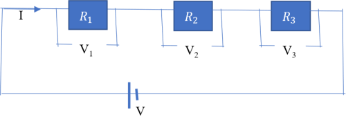
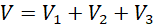
The sum of the voltage drop across each resistor is equal to the supply voltage i.e.
 (i)
(i)
Given that the supply current I passes through all the resistors, it follows that;
 (ii)
(ii)
 (iii)
(iii)
 (iv)
(iv)
Using equations (ii), (iii) and (iv) in equation (i) leads to;
 (v)
(v)
Since V and I are the total voltage and current in the circuit, respectively, then V/I must be the total (effective) resistance R in the circuit. Using this in equation (v) leads to;
 (vi)
(vi)
Equation (vi) gives the effective or total resistance in the circuit when resistors are connected in series.
(2) Resistors in parallel
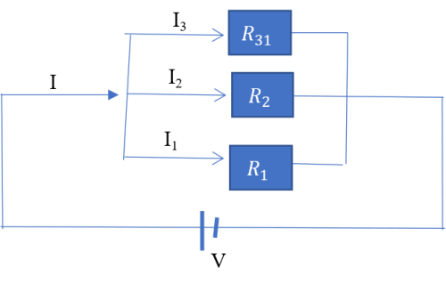
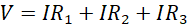
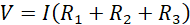
The voltage drop across each resistor is equal to the supply voltage i.e.
 (i)
(i)
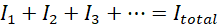
The supply current is however split among the three resistors such that;
 (ii)
(ii)
From Ohm’s law;
 (iii)
(iii)
 (iv)
(iv)
 (v)
(v)
Using equations (iii), (iv) and (v) in equation (ii) leads to;

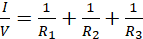 (vi)
(vi)
Since V and I are total voltage and current in the circuit respectively, then V/I must be the total resistance, R, hence;
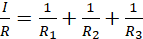 (vii)
(vii)
Equation (vii) is used to evaluate the total resistance in a circuit where resistors are connected in parallel.
EMF, potential difference and internal resistance
EMF E (electromotive force) is the voltage across a cell when it is not connected to an external circuit (cell is not operating), while potential difference V (pd) is the voltage across a cell when connected to an external circuit (cell is in operation). EMF is usually greater than the pd. This is because when the cell is in operation, some of the EMF is used to overcome internal resistance (r) of the cell.
Suppose that an operating cell drives a current I through an external circuit containing a resistor R.
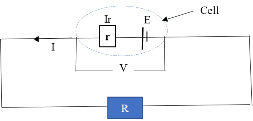
The potential drop due to the internal resistance r is equal to Ir. The potential difference V across the cell is therefore given by:
 (i)
(i)
This potential difference given in equation (i) drives the current (I) through the resistor R hence;
 (ii)
(ii)
Cells in series and in parallel
When cells are connected in series, the current that passes through the load also passes through all the cells. The total (equivalent) EMF in the circuit is equal to the sum of the EMFs of individual cells. The total internal resistance is equal to the sum of internal resistances of individual cells (similar to resistors in series). The advantage of cells connected in series is that they give a greater resultant voltage than individual cells, with the voltage increasing if the number of cells increases. One disadvantage is that a failure in one of the cells breaks the circuit. This may however be viewed as an advantage in some instances since it becomes easy to detect and replace faulty cells.
For cells in parallel, the current through the load is divided amongst the different cells. The total (equivalent, resultant) EMF is equal to EMF of each cell. The total internal resistance is however computed in a manner similar to that of resistors in parallel. The main advantage of cells in parallel is that if one fails, others will continue operating since the circuit will remain closed. Household appliances are usually connected in parallel so that if one of the appliances breaks down, other circuits will not be affected. One disadvantage of a parallel arrangement is that the voltage cannot be increased by increasing the number of cells.
Bulbs in parallel vs bulbs in series
Increasing the number of bulbs in a series circuit decreases the brightness of the bulbs. In a series circuit, the voltage is distributed among all the bulbs, with the sum of the voltages across each bulb being equal to the voltage in the circuit:
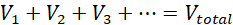
The current through each bulb is however equal to the current in the circuit.

Bulbs in parallel are brighter than bulbs in series. In a parallel circuit, the voltage for each bulb is the same as the voltage in the circuit.

The current in the circuit is however split between the bulbs.
EXAMPLES

2 Comment(s)
Matosh (Sat, 31st May 2025, 5:39 PM)
The notes are superb
Reply
Mourice owii (Mon, 13th May 2024, 5:17 PM)
Thank you
Reply