MAGNETS, ELECTROMAGNETIC INDUCTION & TRANSFORMERS
MAGNETS
A magnet is an object or a material with an associated magnetic field, and capable of attracting a material placed within its magnetic field. Magnetic field is therefore the region around a magnet where its effects can be felt. Not all materials are attracted by magnets. Materials that are attracted are called magnetic materials and include iron, cobalt and nickel. Those strongly attracted are referred to as ferromagnets., a good example being iron filings commonly used in experiments on magnetism. Conversely, non-magnetic materials are not attracted by magnets. Examples are gold, silver, copper and tin. Further, magnetic materials have unpaired electrons in their outer shells while non-magnetic materials have paired electrons in their outer.
Magnets have two poles, the north pole and the south pole.

When freely suspended, a magnetic always come to rest with the its north pole facing North and the south pole facing south. If north poles of two different magnetics are brought close to each other, repulsion occurs. Repulsion also occurs when south poles of two different magnets are brought close to each other. If on the other hand north pole of one magnet and south pole of another magnet are brought close together, attraction occurs. These observations are summarised in two laws of magnets:
- Like poles repel
- Unlike poles attract
It is important to note that a magnet attracts both magnetic materials and the opposite pole of another magnetic. The ability of a magnet to exert force of repulsion or attraction is referred to as magnetism.
What makes a magnet, well, a magnet?
All magnets contain regions called domains where magnetic dipoles align to face the same direction.
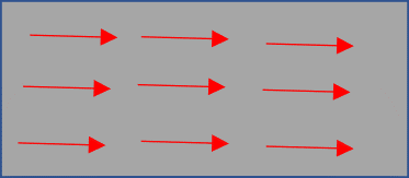
A magnetic dipole is basically a north and south pole separate from each other by the least distance possible. Magnetic dipoles cannot be broken up into independent south north poles. and always exist as a pair. Consequently a magnet cannot be broken up into separate north pole and south pole. Breaking up a magnetic, say into two sections, creates two magnets.
All magnetic materials contain domains although in their um-magnetised state the magnetic dipoles face random directions.
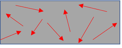
The magnetic dipoles can however aligned in the same direction (magnetise), more or less, through the application of an electric current or by immersing the magnetic material in a magnetic field. The more more aligned the dipoles are, the greater the magnetic strength. Some materials are easy to magnetise (and also easy to demagnetise). A good example is soft iron. A magnetised soft iron has nearly all the dipoles aligned in the same direction and as such forms a very strong magnet.
Magnetic field lines
Magnetic field is the region around a magnet where its effects can be felt. Magnetic field is a vector quantity, represented by lines called magnetic field lines or lines of force.
Properties of magnetic field lines;
- point from north to south
- leave north pole and enter south pole at right angles
- do not cross each other

According to the law of magnetism, like poles repel and unlike poles attract. The field between two attracting and repelling magnets is as shown, respectively.

A magnet is strongest at the poles as opposed to the middle. The stronger the magnet, the higher the magnetic field. Since magnetic field refers to the number of magnetic field lines passing perpendicularly in a unit area, the magnetic field lines will be closer together at the poles where the magnet is strongest than at the centre. Iron fillings follow the magnetic field lines hence the filings will be more concentrated at the ends where the magnet is strongest as opposed to the middle.
Magnetic effect of an electric current and electromagnets
A current has an associated magnetic field whose direction depends on the direction of flow of current. The direction of the magnetic field can be determined using the right-hand grip rule: Imagine gripping the current-carrying conductor with the right hand with the thumb pointing in the direction of current. The curled fingers will indicate the direction of the magnetic field.
When a magnetic material such as soft iron is placed within the magnetic field of a current carrying conductor, it becomes magnetised. A magnet created this way is referred to as an electromagnet. An electromagnet is magnetic only when the current is flowing, and loses the magnetism when the current is switched off. Soft iron is used to make electromagnets because it magnetises and demagnetises easily and also because it concentrates the magnetic field resulting in a relatively strong electromagnet.
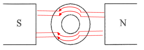
The polarity of an electromagnet depends on the direction in which the current is flowing when viewed from that end. If the direction is clockwise, that end is south pole and if anticlockwise, then the end is north pole.

An electromagnet can be constructed by winding a current carrying conductors around a soft iron core. Such a winding is referred to as a solenoid.
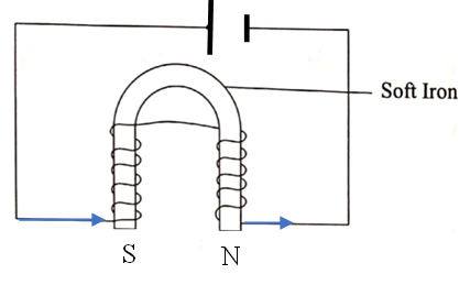
The magnitude of magnetic field B due to a solenoid of length L and N turns carrying current I is given by:
 (i)
(i)
Since μ0 is a constant of proportionality (called permeability of free space), equation (i) may be expressed as;
 (ii)
(ii)
Now
 (iii)
(iii)
Using equation (iii) in equation (ii) leads to:
 (iv)
(iv)
Equation (iv) implies that the strength of the magnetic field around a current carrying solenoid is directly proportional to the;
(i) current,

(ii) number of turns per unit length

Thus, the strength of the electromagnet can be increased by;
- increasing the current (using more cells) in the circuit
- increasing the number of turns per unit length of the solenoid
Current carrying conductor in a magnetic field
When a current-carrying conductor is placed in an external magnetic field, it experiences a force referred to as Lorentz force (hence moves if the force is large enough). The direction of the Lorentz force (same as the direction of motion) is perpendicular to the direction of the current and that of the external magnetic field. It is determined by Fleming’s left-hand rule: If the thumb, fore (first) finger and middle (second) finger are arranged perpendicular to each other with the first finger pointing in the direction of the external magnetic field (B) and the second finger in the direction of current, then the thumb points in the direction of motion/force (F)
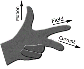
The Lorentz force is due to the interaction of the magnetic field from the external source and the magnetic field produced by the current in the conductor.
As an example consider two straight conductors P and Q connected to a battery and a variable resistor. When the switch S is turned on, current that flows through P and Q .A current has an associated magnetic field whose direction depends on the direction of flow of current. The direction of the magnetic field around P is in the anticlockwise direction while that around Q is in the clockwise direction.
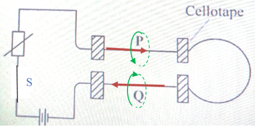
The field cannot cross from one wire to the next. The wires therefore move away from each other (repel).
It is important to note that for two conductors carrying current in the same direction, attraction occurs since the magnetic field is in the same direction. Field lines from conductor can wrap into the other conductor.
ELECTROMAGNETIC INDUCTION
We know that a current carrying conductor has an associated magnetic field. The opposite is also true: a magnetic field can induce current in a conductor. Electricity is induced by a varying (changing) magnetic field, just like magnetism is produced by moving charges. Generation of electricity from a varying magnetic field is referred to as electromagnetic induction.
There are a number of ways of generating electricity from a varying magnetic field:
(i) Moving a conducting coil in a magnetic field
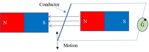
When the wire moves downwards through the magnetic field, electrical energy (or electromotive force EMF, which is electrical energy when no external circuit is connected) is generated and the galvanometer is deflected. When the wire moves up, EMF is induced and the galvanometer is deflected though in the opposite direction. This means that the direction of the induced EMF and the subsequent induced current reverses when the direction of motion of the wire changes. The induced EMF and current are said to be alternating and are referred to as alternating EMF and alternating current (ac) respectively.
When the speed of the wire, or the strength of the magnets are increased, the deflection of the galvanometer increases, indicating that more EMF is induced. When a wire with multiple turns (a coil) is used instead of one straight wire, deflection increases, with an increase in the number of turns leading to a greater deflection. This means that increasing the number of turns in a coil of wire leads to the induction of more EMF. When the wire is kept stationary in the field, or when moved sideways (as opposed to up and down), the galvanometer remains at zero deflection which means that EMF is not induced in the wire.
Thus, electricity is only generated if the wire cuts the magnetic field lines. Other factors constant, the magnitude of the induced EMF is maximum when the wire cuts the magnetic field at right angles, reduces as the angle reduces and reaching a minimum (zero) when the angle is zero (wire moving parallel to the field). The EMF then starts increasing when the wire passes the zero mark but with polarity and hence the direction of current reversed.
Electricity generation by moving a conductor in a magnetic field is the main method used in the generation of mains electricity. The power is categorised based on what is used to turn the wires (turbines) in the magnetic field;
- Hydro-power – falling water is used to turn turbines
- Thermal power – thermal energy (e.g. generated from petrol or burning coal) is used to heat water, generate steam which then turn the turbines.
- Geothermal power – steam from the ground is used to turn turbines
- Nuclear power – heat produced during nuclear reactions is used to generate steam that drives the turbines.
- Wind power – wind is used to turn turbines
(ii) Moving a magnet in a conducting coil:
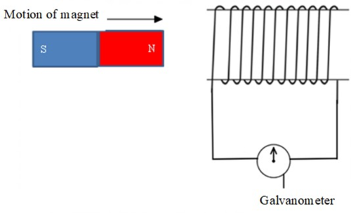
When the magnet moves into or out of a conducting coil, the galvanometer is deflected (although in different directions). When the magnet is left stationery in the coil, the galvanometer is not deflected. The reason for this is that as the magnet moves in and out of the coil, the magnetic field around the magnet cuts through the wire thereby exposing the wire to a varying magnetic field. If the magnet is moved in and out at a higher speed, the deflection of the galvanometer increases indicating that more EMF is induced. If the number of turns of the coil are increased, the deflection of the galvanometer increases too. Also, if a stronger magnet is used, more EMF is induced. Thus, magnitude of the induced EMF increases with;
- increase in the speed of the magnet through the coil,
- increased number of turns in the coil, and
- strength of the magnet.
How does a moving magnet induce EMF in a coil?
EMF is induced in such a way that as a north pole enters the coil, the entry side acquires a north pole and as the magnet moves out, the same side acquires a south pole. This means that work has to be done to overcome repulsion during entry and attraction during exit. It is this work that is converted to electrical energy.
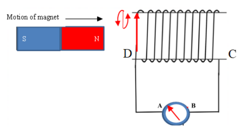
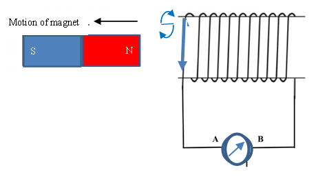
The polarity of the magnetic field associated with a current carrying conductor depends on the direction of flow of current. The direction of the induced current when the magnet moves into the coil is opposite the direction of the current when the magnet moves out hence change in the deflection of the galvanometer.
(iii) Gradually increasing or decreasing current
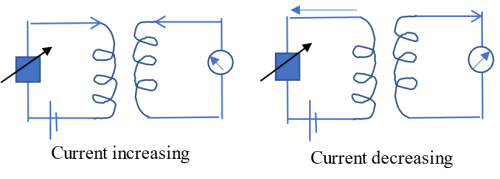
Gradually increasing or decreasing coil in one coil (primary) leads to the induction of EMF in a second coil (secondary) within the magnetic field of the primary coil. As the current in the primary coil changes, the magnetic field around it also changes leading to the induction of EMF in the secondary coil. If the current in the primary coil is kept constant, no EMF is induced in the secondary coil. A similar effect is also observed in a secondary coil the instant a switch in the primary coil is switched on (current increases from zero to maximum), and the instant the switch is closed (current falls from maximum to zero).
Faraday's Laws of electromagnetic induction
Electromagnetic induction was first observed by Faraday. Faraday summarised his observations into two laws which he called Faraday’s laws of electromagnetic induction.
Faraday’s first law : EMF is induced when a coil is placed in a changing magnetic field
Faraday's second law: the magnitude of the induced EMF is directly proportional to the rate in which the magnetic flux φ (number magnetic field lines B passing normally in an area A implying, φ=BA is changing, i.e.
 (i)
(i)
For a coil of N turns, the magnitude of induced EMF is directly proportional to the rate of flux linkage where flux linkage = Nφ. That is;
 (ii)
(ii)
If N is constant (fixed number of turns), then:
 (iii)
(iii)
According to Lenz law, the induced EMF generates current that flows in a direction that opposes the change causing it. Combining Faraday’s equation (iii) and Lenz laws leads to:
 (iv)
(iv)
The negative takes care of Lenz law.
Considering that;
 (v)
(v)
where B is the magnetic field and A is the cross-section area of the coil perpendicular to the magnetic field, equation (iv) may be expressed as;
 (vi)
(vi)
Equation (vi) implies that induced EMF can be increased by
- increasing the number of turns in the coil
- increasing the cross-sectional area of the coil
- using stronger magnets (to increase the magnetic field B)
- increasing the rate of change of magnetic field (e.g., moving the coil in the magnetic field at a faster rate).
Power loss during transmission
The peak power P generated from a varying magnetic field is given by:
 (i)
(i)
where V is the peak voltage and I the peak current.
However, not all the power generated reaches the end user as some of it is lost during transmission. This is because when current passes through a wire, heating (Joule’s heating) occurs resulting in power loss. For a wire of resistance R carrying peak current I power loss Ploss is given by;
 (ii)
(ii)
From equation (i) it is clear that if the resistance of the wire, and/or the current passing through the wire are high, power loss will be equally high. This is because a higher amount of work will be required required to move current through the wire of high resistance as well as in cases where a high current is involved. Power meant for transmission does this work hence the power loss. Thus, for power loss to be minimised during transmission;
- Wires/cables of low resistance used.
- Current should be as low as possible and
To reduce the power loss during transmission therefore, the resistance of the transmitting cables and the current should be as low as possible.
The resistance R of a wire is:
- inversely proportional to cross-section area A, ie.

- directly proportional to length l, ie.

Combing the two equations leads to;


where γ is a constant of proportionality called resistivity. Different materials naturally have different magnitudes of resistivity. For example, aluminium wire has a higher resistivity than a copper wire of equal dimensions. This means that the best way to reduce the resistance of aluminium power lines (and hence the power loss) is by using thick cables (cables with a large cross-sectional area).
Reduction of current is achieved by increasing voltage to very high values, a process called stepping up voltage. Most electrical appliances use low voltage power. Before being distributed to consumers therefore, the voltage must be reduced to the desired voltage, a process called stepping down voltage. Power is stepped up and down through electromagnetic induction. As such, only ac voltage can be used due to the associated changing magnetic field.
Transformers
A transformer is a device used for stepping up voltage for transmission or stepping down voltage for distribution to the end user. This happens without change of frequency. It basically consists of two coils of wire wound on a laminated core made of a magnetic material, for example soft-iron or steel. The two coils make up the primary and secondary coil. The primary coil is connected to the ac source while the secondary coil is connected to some output. Though the two coils are not physically connected, they are arranged in such a way that the secondary coil lies within the current-induced magnetic field of the primary coil. Consequently, the changing magnetic field of the primary coil induces EMF in the secondary coil, a process referred to as mutual induction (defined as induction of EMF in one coil due to changing magnetic field of another coil).
According to Faradays first law, a changing magnetic flux φ induces EMF (voltage) in a secondary coil linked to the magnetic field of the primary coil. According to the second law, the magnitude of the induced EMF depends on the number of turns and the rate of change of magnetic flux, summarized mathematically as;

Rate of change of magnetic flux constant, the magnitude of induced EMF solely depends on the number of turns in the secondary coil. There are thus two types of transformers:
- Step-up transformer
- Step-down transformer
Step-up transformer
For a step-up transformer, the number of turns (windings) in the secondary coil (Ns) is greater than the number of turns in the primary coil, i.e. Ns>Np.
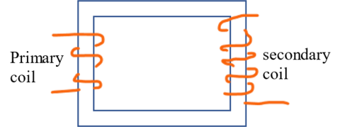
As the magnetic field around the primary coil changes, EMF is induced in the second coil. Rate of change of magnetic flux constant, the magnitude of EMF induced in the secondary coil depends the number of turns. Given that Ns>Np, it follows that the EMF induced in the secondary coil is greater that the source EMF.
Step-down transformer
The number of turns in the secondary coil is less than that in the primary coil, i.e., Ns<Np.

In accordance with Faraday's law therefore, the induced EMF is less than the source EMF.
For both step-up and step-down transformer and assuming no power loss takes place , input power (power in primary coil) is equal to output power (power in secondary coil). If Vp and Ip be the input voltage (EMF) and current in the primary coil, respectively, then the power input Pin is equal to:
 (iii)
(iii)
And if Vs and Is be the output voltage and current in the secondary coil, respectively, the power output Pout is equal to;
 (iv)
(iv)
Assuming no power loss (meaning the transformer 100% efficient), it follows that equations (iii) and (iv) are equivalent. Hence
 (v)
(v)
 (v)
(v)
If Np and Ns be the numbers of turns in the primary and secondary coils respectively, then by Faraday's law;
 (vi)
(vi)
 (vii)
(vii)
Dividing equation (vi) by equation (vii) gives:
 (viii)
Equations (v) and (viii) can be condensed to;
 (ix)
(ix)
Transformer efficiency, power loss in transformers and correction
In reality, transformers are not 100% efficient. This means that power input is not equal to power output,
 .
.
The power in the primary circuit is always higher than the power in the secondary circuit. The ratio of the output power to the input power is referred to as the efficiency of the transformer, often expressed as a percentage, i.e.,


A transformer loses power due to;
- Current flowing in the coils (load/copper losses)
- Magnetic field in the core (no load/iron losses)
(1) Copper losses: Copper losses are mainly due to Joule heating (heat losses) that occurs as current flows through the wires. Power lost due to this heating in the coils is given by;

This power loss can only be addressed by using coils of low resistance. Resistance (R) of the coil depends on the resistivity (γ) of the coil material, the cross-sectional area (A) of the coil and its length (l) according to the formula;

Some materials such as copper are naturally good conductors hence have low resistivity. Additionally, wires of larger cross-sectional area offer lower resistance to the flow of current. Using copper coils of a large cross-sectional area can therefore help in addressing power loss through heating. Copper losses are load (current) dependent. The higher the current, the higher the losses.
(2) Iron (no-load) losses: These occur in the core as a result of the magnetization of the core caused by the alternating current. They are independent of the load. Iron losses fall under two main categories;
- Hysteresis losses
- Eddy current losses
Hysteresis losses occur due to the periodic reversal of the magnetic field in the core of the transformer as a result of the alternating current. Power is required to reverse the direction of this magnetic field. This power, dissipated in the form of heat, is referred to as hysteresis loss. The losses increase with the area of the hysteresis loop. Magnetic materials with small hysteresis loop area, for example silicon steel, are therefore used for the construction of transformer cores to minimize these losses.
Eddy current losses on the other hand arise when the change in the direction of the electromagnetic field in the transformer core induces EMF in the core. The induced EMF produces currents within the core called eddy currents. Since the core has some internal resistance, the eddy currents lead to power loss (Ploss=I2R) through heating. To minimise power (P) loss through eddy currents, the magnitude of the eddy currents (I) should be as low as possible. This is achieved by creating transformer core which has a very high resistance (R). A high resistance core is attained by laminating the core (creating a core composed of multiple layers as opposed to one solid layer), with each lamination insulated from the next by means of a thin varnish coating. Each lamination therefore acts as a separate core of a small cross-sectional area thus offering a high resistance to the flow of eddy currents (resistance varies inversely with the cross-sectional area. The smaller the cross-sectional area, the higher the resistance).
Flux leakage losses: These occur in both the primary and secondary coils when a small portion of the magnetic flux links one coil but not both.
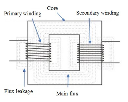
Flux leakage in a transformer can be minimized by winding the primary and secondary coils over each other.
EXAMPLES


2 Comment(s)
Matosh (Sat, 31st May 2025, 5:57 PM)
Notes are better
Reply
Matosh (Sat, 31st May 2025, 5:57 PM)
Notes are better
Reply