OPTICS: MIRRORS, REFRACTION, LENSES, INTERFERENCE
INTRODUCTION
Light is a form of electromagnetic waves that lies between infrared (IR) and ultraviolet (UV) bands in the electromagnetic spectrum, often referred to as the visible region.

Light is made up of seven (7) colours of light namely, in the order of decreasing wavelength, red, orange, yellow, green, blue, indigo and violet. Unlike other forms of EM radiation, the colours of light are visible to the human eye. When all the colours of light combine, they form what is referred to as white light. Sunlight is one example of white light.
Light has a dual nature in that it exhibits both particle characteristics as well as wave characteristics. According to the particle theory, light is made up of mass-less particles called photons. Each photon carries discrete amount of energy E which solely depends frequency f , i.e. E∞f hence E=hf (h Planck’s constant). Characteristics of light only explained by particle theory include photoelectric effect and black body radiation.
The wave theory postulates that light is a transverse wave that obeys the general wave equation v=λf, where v is the velocity, λ the wavelength and f frequency. Properties of light that can only be explained by wave theory make up the 7 basic properties of light namely;
- Reflection
- Refraction
- Interference
- Diffraction
- Polarization
- Dispersion
- Scattering
All colours of light travel at the same constant speed (c) in vacuum with c=3×10⁸ m/s. The speed of the different colours of light is however different (and lower ) in denser media such as water and glass. Given that frequency is independent of the propagating medium, it follows that by the wave equation v=λf, velocity of the different colours of light in optically denser media is directly proportional to the wavelength. Red has the longest wavelength and therefore the fastest denser media while violet has the shortest wavelength and therefore the slowest.
Definition of terms associated with light
Wavefront : This is the locus of all points in a wave having the same phase of oscillation, e.g. apexes of crests. Wavefronts represented by equally spaced lines in any one medium with the distance between two consecutive wavefronts equal to λ. Besides, wavefronts can be
- curved (spherical wavefronts) – e.g. those from a point source
- Straight (plane wavefront) e.g. from a far of source or straight source.
Ray: This is a line drawn perpendicular to the wave front that indicates the direction of travel of the wave.

Incident ray – a ray of light directed towards a surface or interface.
Normal (N) – Imaginary line perpendicular to the surface or interface at the point of incidence.
Angle of incidence (i)– angle between the incident ray and the normal
Point of incidence (O) -The point at which the light hits the surface.

REFLECTION OF LIGHT
Reflection is the bouncing of light off a reflecting surface.
- Reflected rays - rays that bounce of the reflecting surface angle they
- Angle of reflection – angle reflected rays make with normal.
Other than a perfect black body (a hypothetical body that absorbs all light (or any form of electromagnetic radiation) that falls on it), all objects reflect some amount of light that falls on then. The degree of reflection depends on the nature of the surface with shiny or bright surfaces being better reflectors than dull dark ones.
Reflection humans and animals to see objects. For the eye to detect and make out the shape of the object, light which falls on an object must be reflected to the eye. What we perceive as the colour of the object is the colour reflected to our eyes. For this reason, the same object appears to be coloured differently when viewed in different colours of light, for example disco lights. Objects that absorbs all colours of light appear black while those that reflects all light appear white.
Laws of reflection:
Two laws define the reflection of light. These are:
- Angle of incidence equals angle of reflection i=r
- At the point of incidence, the incident ray, the reflected ray and the normal all lie on the same plane

(1) Reflection by plane mirrors
Characteristics of images formed by plane reflecting surfaces (e.g. a plane mirror):
- the image is laterally inverted (left becomes right)
- the object distance (u) equals the image distance (v)
- the image is virtual (cannot be formed on a screen)

Ray diagram: Rays that made up virtual images as well as the images themselves are represented using broken lines.

(2) Reflection by curved mirrors
Curved mirrors are mirrors made from sections of a hollow sphere. They are of two types:
- Concave mirrors which are silvered on the outside
- Convex mirrors which are silvered on the inside.

Terms associated with curved mirrors
Pole P- it is the centre of the mirror.
Centre of curvature C- centre of sphere of which the mirror is part.
Radius of curvature R - radius of sphere of which the mirror is part.
Principal axis- line drawn through the pole of the mirror and the centre of curvature.

Principal focus F –Defined differently for the two mirrors
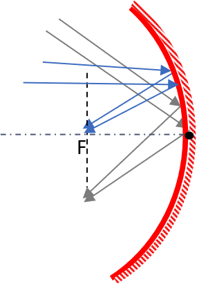
- for a concave mirror, it is the point at which all rays parallel and close to the principal axis converge at after reflection. I
- For a convex mirror, it is the point at which all rays parallel and close to the principal axis appear to diverge from after reflection.
Focal length f - distance between the pole of the mirror and its focal point.
Focal points - point where parallel rays not parallel to axis also converge at (or appear to diverge from).
Focal plane- it is a plane perpendicular to the principal axis and passes through the focal points.

Ray diagrams
These are used for graphical representation of image formation. The following symbols to represent the concave and convex mirrors respectively.

When drawing ray diagrams the following rays are used.
- All incident rays parallel to the principal axis are reflected so as to pass through (or appear to come from) the principal focus.
- All incident from or appear to come from the principal focus are reflected parallel to the principal axis.
- All incident rays through (or appear to come from) the center of curvature are reflected through the same path

It is important to note that rays produced behind the mirror form virtual images and as such are represented using broken line.
Images formed by concave mirrors
A concave mirror is also referred to as converging mirror since it reflects parallel rays to a point. If this point lies on the principal axis, it is called principal focus F. Principal focus is real and is located in front of the mirror.

A concave mirror forms both virtual (cannot be formed on a screen, formed opposite the object relative to the mirror) and real images (can be formed on a screen, formed on the same side as the object) depending on the position of the object relative to the mirror.
Characteristics of images formed by concave mirrors


Images formed by convex mirrors
A convex mirror reflects parallel rays such that they appear like they are form a principal focus behind the mirror. Principal focus is virtual and is located behind the mirror.

A convex mirror forms a virtual image irrespective of the position of the object relative to the mirror.

A convex mirror is used as a driving mirror or for security reason in supermarkets for two reasons;
- It has a wide scope of view. This means that objects within a wide area can be viewed in the mirror
- It forms virtual upright images
The draw back of a convex mirror as a driving mirror is that it forms images which are smaller than the objects. The objects when viewed through the mirror therefore appear further away than they are. (We perceive hoe far objects are based on their apparent size. Far off objects appear smaller because the image formed on the retina of our eyes is smaller. The size of the object appears to become bigger as the object gets closer to the observer).
Mirror formula
The mirror formula provides the relationship between u, v and f. Consider the ray diagram shown where f is the focal length (distance between centre of the mirror (pole) and the principal focus; u is the distance between the object and the mirror (object distance); v is the distance between the image and the mirror (mirror distance).

Triangles EDF and FPM similar triangle
 (i)
(i)
But PM=AB hence
 (ii)
(ii)
But DF=DP-FP so
 (iii)
(iii)
BAP and DEP similar triangles;
 (iv)
(iv)
Equating (iii) and (iv)
 (v)
(v)
Now DP=v, FP=f, PA=u

 (vi)
(vi)
Divide through by v

 (vii)
(vii)
Equation (vii) represents curved mirrors the formula and is applied to both concave and convex mirrors. The focal length of concave mirrors is assigned a positive value while that of a convex mirror is assigned a negative value given that the former is real while the latter is virtual.
It can be shown that if f be the focal length of a given curved mirror and R its radius of curvature, then;
 (viii)
Magnification
This the number of times the image is larger than the object;

By equation (iv)

Hence
 (ix)
(ix)
Experiments to determine focal length of a concave mirror
There are various experimental methods that can be used to determine the focal length of a concave mirror, among them;
By use of mirror formula
- Focusing a far-off object
Using the mirror formula
- Place an object between a concave mirror and a screen.
- Vary the distance between the object and the concave mirror until a sharp image is formed on the screen.
- Measure the distance between the object and the mirror (u)
- Measure the distance between the image (screen) and the mirror (v).
- Use the mirror formula

to determine the focal length f.
Focussing a far-off object
- Parallel rays (rays from far-off objects are more or less parallel) always converge at a point on the focal plane (plane passing through the principal focus):
- Use the concave mirror to focus a far-off object on a screen.
- Adjust the distance between the mirror and the screen until a sharp image is formed.
- Measure the distance between the mirror and the screen.
- This distance corresponds to the focal length of the mirror.
REFRACTION OF LIGHT
When a ray of light moves from one medium to another of different optical density, its velocity changes., and if the entry is oblique, the direction also changes. This change in velocity of light leads to what is referred to as refraction. Refraction may therefore be defined as the change in direction (bending) of light when it moves from one medium to another of different optical density.
A stick immersed in water appears bent at the interface of water and air due to refraction of light that bounces of the stick.

This is because for one to see the section of the stick immersed in water, a ray of light must bounce off that section, travel through water before immerging into the air. This change in velocity causes the stick to appear bent at the water-air boundary.
Terms associated with refraction of light
Incident ray - ray striking the interface between the two media
Point of incidence - point the incident ray strikes the interface
Normal - line drawn at the point of incidence and normal to the two media
Angle of incidence - angle between the incident ray and the normal
Angle of refraction - angle between the refracted ray and the normal
NOTE: When a ray of light moves from a less-dense (rarer) medium to a denser medium, it bends towards the normal and vice-versa.

Laws of refraction
- The incident ray, the refracted ray and the normal lie on the same plane at the point of incidence (O).
- .Snell’s law: the ratio of the sine of angle of incidence to the sine of angle of refraction is a constant. The constant is called the refractive index η second medium (refracting) medium with respect to the first medium.

Relationship between refractive index, velocity and wavelength of light
When a ray of light moves from one medium to another of different optical density, its velocity changes. Light is a form of electromagnetic wave and has its highest velocity at 3 × 10⁸ m/s. This velocity is commonly referred to as velocity of light in space and is usually by the letter c.
When the light moves from one medium to another medium of higher optical density, its velocity reduces. The ratio of velocity of light in the first medium (say v1) to the to velocity of light in the second medium (say v2) is equal to the refractive index of the second medium with respect to the first, abbreviated 1η2. Hence
 (i)
(i)
The frequency of light f is independent of the medium of propagation but the wavelength is not. If λ1 be the wavelength of light in the first medium and λ2 in the second medium, then by the wave equation (v=λf) equation (i) may be expressed as:

 (ii)
(ii)
Comparing equations (i) and (ii) leads to;
 (iiii)
According to equation (iii), a reduction in velocity of light in the denser medium must be accompanied by a proportionate change of wavelength in the same medium. This means that when light moves from a less dense to a denser medium, its wavelength reduces.
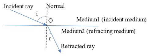
Definition of terms associated with refraction
Suppose a ray of light in air enters a second medium (say water) from some first medium (say air) at some point on the air -water interface. The ray that strikes the interface is referred to as the incident ray while the ray that progresses into the water is called the refracted ray. An imaginary line perpendicular to the interface at the point the incident ray enters water is called the normal. The point of intersection of the incident ray, the normal and the refracted ray is called the point of incidence, O. The angle between the incident ray and the normal is called the angle of incidence, i, while that between the refracted ray and the normal is the angle of refraction, r.
When a ray of light enters a denser medium at an angle of incident greater than zero (obliquely), the ray in the denser medium bends towards the normal (refraction is often defined as the change in direction of light when it moves from one medium to another of different optical density). In this case;

Laws of refraction
There are two laws that are associated with refraction:
1st law: This states that the incident ray, refracted ray and the normal all lie on the same plane at the point of incidence
2nd law: The second law is also referred to as Snell’s law: It states that the ratio of sine of angle of incidence to sine of angle of refraction for a pair of media is constant. This constant is referred to as the refractive index of the second medium (refracting medium) with respect to the first medium (incident medium);
 (iv)
(iv)
By equations (i)and (ii), it follows that;
 (v)
(v)
It is important to note that;
- A ray that enters a second medium normally (parallel to normal) passes through un-deviated.
- When a ray moves from a denser to a less dense medium, it bends away from the normal.
Say a ray of light moves from air to glass then back to air as shown. Suppose that aηg is the refractive index of glass with respect to air and gηa the refractive index of air with respect to glass.

It follows that for the ray incident on face AB:
 (i)
(i)
For the ray incident on face CD;
 (ii)
(ii)
From trigonometry; ia=ra and rg=ig. With this in mind, equation (ii) may be written as;
 (iii)
(iii)
Comparing equation (iii) and (i) leads to;
 (iv)
(iv)
Equation (iv) represents the law of reversibility of light travel.
Apparent and real depth
If for example a coin is placed at the bottom of a long cylinder filled with water, it appears closer to the surface than it really is when viewed from the surface (top). This is attributed to the refraction of light. As the light moves from water to air, it bends away from the normal.

For us to see an object, light must bounce off, or appear to bounce off, the object straight to our eyes. When we view an object in a denser medium, rays bouncing off the object appear to come from a point closer to the surface as opposed to where the object is actually situated. The object appears closer to the surface than it really is. The actual distance between the surface of the denser medium and the object is referred to as real depth, while the distance between the surface of the denser medium and where the object appears to be is called apparent depth. It can be shown that the refractive index of the denser medium with respect to air, ηdenser is;

Critical angle and total internal reflection
When a ray of light moves from a denser medium (say glass) to a less dense medium (say air) it bends away from the normal. This means that the angle of incidence is always smaller than the angle of refraction. Critical angle (C) refers to the angle of incidence when the angle of refraction is 900.

For a ray of light moving from air to glass, the refractive index of glass with respect to air, aηg is given by;
 (i)
(i)
If the ray moves from the same glass to air, and if gηa is the refractive index of air with respect to glass, then;
 (ii)
(ii)
Comparing equation (ii) and (iii), it follows that;
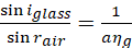 (iii)
(iii)
Now iglass=C(critical angle) when rair=900 hence;
 (iv)
(iv)
But sin900 = 1 hence
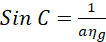 (v)
(v)
When the angle of incidence increases beyond the critical angle, total internal reflection takes place.

Conditions for total internal reflection to occur:
- Ray of light must move from a denser to a less dense medium
- Angle of incidence must exceed the critical angle
LENSES
A lens is a a piece of transparent material, either plastic or glass, moulded in such a way that light is refracted when it passing through it, and the refracted light can be focussed in such a way that it forms an image. A lens basically consists of two polished surfaces with one or both sides curved. Our discussion will focus only on lenses that are curved on both sides, the so-called curved lenses or thin lenses.
There are two types of curved lenses:
- convex lens (converging, bulges at the centre)
- concave lens (diverging, thin at the centre).
The lenses may be thought of as composed sections of two transparent spheres joined together as shown. The centre of each sphere is called the centre of curvature while the imaginary line joining the centre of the spheres of the two spheres parts of which make up the lenses is called the principle axis. The middle of the lens is the pole. The distance between the centre of curvature and the pole is the radius of curvature R.

A convex lens is a converging lens in that all parallel rays incident on it parallel to the principal axis are refracted so as to converge at a point on the principal axis called the principal focus (F). The distance between the principal focus and the lens is called focal length, f. It can be shown that the radius of curvature of a lens is twice its focal length, i.e., R = 2f. If the rays are not parallel to the principal axis, they converge at a focal point on the focal plane. A focal plane is represented by a line passing through the principal focus and perpendicular to the principle axis. A convex lens forms virtual or real images depending on the position of the object relative to the lens. The lens has a real (positive) focal length.
A concave lens on the other hand diverges all parallel rays falling on it in such a way that they appear as if they are coming from a point on the opposite side (principal focus if point is on the principal axis). It only forms virtual images irrespective of the position of the object. The focal length of a concave lens is virtual (negative).
Ray diagrams
Formation of images by lenses is represented graphically by ray diagrams. To obtain the ray diagram, any two of the following three rays may be used;
Convex lens:
- Rays through the centre of the lens pass through un-deviated
- Rays parallel to the principal axis are refracted through the principal focus
- Rays through the principal focus are refracted parallel to the principal axis

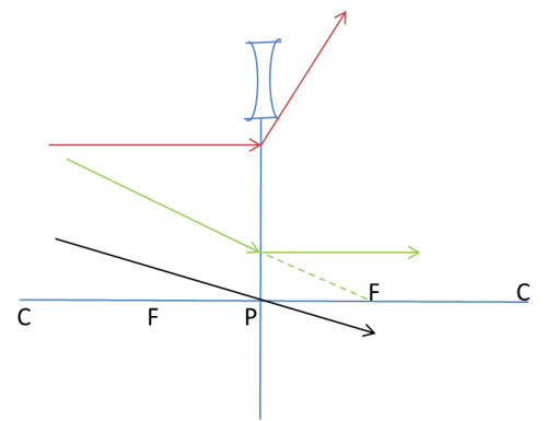
NOTE: For a convex lens to form a virtual image, the object must be placed between F (principal focus) and the lens. The virtual image is always bigger than the object. To locate the object:
- Draw a line from the tip of the image directed towards F on the right (line 1)
- At the point where the line (1) cuts the lens (X), draw a line parallel to the principal axis (line 2).
- Draw a line from the tip of the object that passes through the pole (O) of lens (line 3)
- Draw the object with its tip at the intersection of lines (2) and (3).

It is important to note that virtual images and virtual rays are represented using broken lines while real images (and objects) and rays are represented using solid lines. All lines representing rays must be directed with the arrow head pointing in the direction of travel.
Concave lens
- Rays through the centre of the lens pass through un-deviated
- Rays parallel to the principal axis are refracted as if they are coming from the principal focus on the same side as the rays
- Rays directed towards the principal focus on the other side of the lens are refracted parallel to the principal axis
Images formed by a convex (converging) lens


For a convex lens to form a virtual image, the object must be placed between F (principal focus) and the lens. The virtual image is always bigger than the object.
Images formed by a concave (diverging) lens

All images formed by a concave lens bear these characteristics.
Lens formula
All lenses obey the lens formula (similar to the mirror formula);

Where f is the focal length, u is the distance of the object from the lens and v is the distance of image from the lens. Real distances are taken to be positive (object distances, distances of real images, focal length of convex lens,) while virtual distances are taken to be negative (distances of virtual images and focal length of concave lens).
Magnification
Image magnification M refers to the ratio of size (e.g. height) of the image to that of the object (or how much an image is bigger than the object). If for example h0 be the height of the object and hi the height of the image formed, then the magnification M is given by:
 (i)
(i)
It can be shown that if u be the distance of the object from the lens and v the distance of image from the lens, then;
 (ii)
(ii)
Comparing equations (i) and (ii) shows that;
 (iii)
(iii)
If the M > 1 the image is larger than the object; M = 1, the image is of the same size as the object and if M < 1 the image is smaller than the object.
Optical instruments
(i) Simple microscope (magnifying glass)
This is basically a convex lens with the object placed between the lens and principal focus.

(ii) Compound microscope:
Consists of two convex lenses, the objective lens and the eyepiece, placed some distance apart. The objective lens has a short focal length (fo) and therefore is more rounded. It is arranged in such a way that it forms a magnified real image of the object. The eyepiece lens on the other hand has relatively longer focal length (fe)and as such thinner. It is arranged in such a way that the image of the objective lens, which acts as the object of the eyepiece falls between its pole and principal focus. The eyepiece therefore acts as a magnifying glass.

3. The human eye
Works much the same way as a camera. It consists of :
- Cornea – clear front surface of the eye. Focuses light same as camera lens.
- Iris controls amount of light entering through the pupil much like diaphragm and aperture of a camera.
- crystalline lens located directly behind the pupil focuses image on the retina. Through a process called accommodation, this lens helps the eye automatically focus on near and approaching objects, like an autofocus camera lens.
- retina — the light-sensitive inner lining of the back of the eye – like image sensor of a camera. Retina converts optical images into electronic signals.
- The optic nerve then transmits these signals to the visual cortex — the part of the brain that controls our sense of sight.
NOTE: Pinhole camera
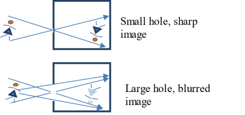
A pinhole camera is a simple camera that operates without a lens. It is basically a light-proof box with a very small aperture. Light from an object enters the camera through the small aperture and forms an inverted image on the other end of the box.
The clarity (sharpness) of the image formed by a pinhole camera depends, among other factors, on the size of the aperture/hole. A small hole concentrates light entering the camera within a small region resulting in a sharp image. An extended hole on the other hand allows a lot of light to enter the camera. This light is spread over a large area making the image formed blurred.
If the aperture is too small, light entering the camera is diffracted (spreads out) leading to the formation of a blurred image. If the distance between the aperture and the screen (length of the camera) is increased, the image size increases although it may become blurred.

If the distance between the object and the pinhole is reduced, the size of the image becomes bigger.

Similarities between working of human eye and that of camera
| Human Eye | Camera |
| The pupil lets in light into the eye. | The aperture lets in light into the camera |
| The amount of light entering the eye is regulated by the iris | The amount of light entering the camera is regulated by the diaphragm. |
| Real inverted image formed on the retina | Real inverted image formed on the film or sensors |
| The eye contains a lens. | Camera also contains a lens. |
| A choroid layer absorbs light thereby limiting reflection. | Inside of camera painted black to limit reflection. |
Differences between working of human eye and that of camera
| Human Eye | Camera |
| Focal length can be changed (changed by the contraction and relaxation of ciliary muscles. This subsequently leads to change in the distance between the lens and the retina). | Focal length is fixed |
| Retina retains the impression for a fraction of a second | Image on the film is retained permanently. |
| Same retina can be used to view unlimited (infinite) images | The film has a finite number of images that it can hold. |
Lens related eye-defects and correction
(i) Near-sightedness (myopia)
A short-sighted person is only able to focus objects that are nearby.

An eye as able to focus objects at different distances by varying the curvature of the lens. To focus nearby objects, the eye lens is made more rounded by the ciliary muscles thereby reducing the focal length. The image distance consequently reduces. To focus far off objects, the lens becomes less rounded hence the focal length increases. The image distance thus increases. Short-sightedness occurs when the lens becomes more rounded and hardened. As such, the lens is not able to focus far off objects as the image rays converge in front of the retina.

Myopia is corrected using a concave (diverging) lens.

(ii) Far-sightedness (hyperopia)
A far-sighted person is only able to see far off objects.

The lens is not able to focus nearby objects on the retina as the image rays converge behind the lens.

Far sightedness is corrected using a convex (converging) lens.

INTERFERENCE OF LIGHT
When two waves are at the same place at the same time, the resultant effect is equal to the combined effects of the two waves governed by the superposition principle. This combination is referred to as interference. For interference between waves to be observed
- The two sources of waves must be coherent – produce waves with a constant phase difference between them hence of equal frequency.
- The interfering waves should have nearly equal amplitudes to allow for contrast.
Young’s double slit experiment
Thomas Young was the first scientist to demonstrate interference of light. The arrangement for his experiment consisted of a single source of monochromatic light (light of one wavelength) passing through double slits to ensure coherence of interfering light.

The single slit S diffracts (spreads out) light to slits 𝑆1 and 𝑆2 which act as coherent sources. Light from the coherent sources overlap and interference occurs leading to a series of equally spaced bright fringes alternating with dark fringes. The bright fringes are formed when crest of one wave and crest of the other (red and red) and trough of one wave and trough of the other (blue and blue) arrive on the screen at the same time. The two waves are said to interfere constructively. A bright fringe that forms at the centre of the screen (in between the slits) is referred to as the central bright fringe. A dark fringe on the other hand forms when crest of one wave and trough of the other arrive on the screen at the same time. The two waves are said to interfere destructively. A sequence of dark alternating with bright fringes are formed on either side of the central bright fringe.
For a bright fringe to be formed, the path difference (difference in wavelength) between rays reaching the screen must be equal to an integral multiple of wavelengths, i.e.
 (i)
(i)
where n = 0 1, 2……
n = 0 corresponds to the central bright fringe while n = 1, n = 2, n = 3… corresponds to 1st, 2nd, 3rd,…..,nth order bright fringe respectively.
For a dark fringe to be formed, the path difference must be odd multiples of half wavelengths, i.e.
 (ii)
(ii)
where m = 1, 2……
Dark fringes start at 1st order to second order etc (there is no central dark fringe).

Fringe separation formula
Suppose that two sources of monochromatic light (two slits) of wavelength λ are a distance a apart. Suppose too that n bright fringes are formed on a screen a distance D from the slits.

The path difference between ray S1P and S2P is equal to S2R, i.e.
 (i)
(i)
If P be the nth bright fringe, then;
 (ii)
(ii)
Triangles S1S2R and NPO and are similar triangles hence:
 (iii)
(iii)
But;
 (iv)
(iv)
 (v)
(v)
 (vi)
(vi)
Also, assuming
 (vii)
(vii)
Then equation (iii) becomes;
 (viii)
where n = o, 1, 2, …… bright and darks are equally spaced
It is important to note that;

EXAMPLES

1 Comment(s)
Onchiri (Fri, 1st Aug 2025, 7:14 AM)
Excellent notes.......thanks
Reply